Tractor Ac System Diagram
Tractor ac system diagram. Distributor Antique Tractor Blog 6 Volt to 12 Volt Conversion Help Antique Tractor Blog 6 to 12 volt. JD E cab loader MX10 cutter. John Deere Tractor Wiring Harness.
Repair green tabs is covered in TM-1353 formerly TM-1257 40504250 and 4450 Tractors TM-1354 formerly TM-1258 4650 and 4850 Tractors CTMI 6466 Engines and. Performance is dramatically reduced with dirty cab air filters. The ac rocker switch provides 12 volts to this thermostat control first before it goes to the pressure switch.
AND 4850 TRACTORS TECHNICAL MANUAL TM-1259 SEP-87 CONTENTSOPERATION AND TESTS This manual covers Tractor Operation and Tests yellow tabs. On John Deere 5083e Ac Blower Wiring Diagram. According to temperature conditions.
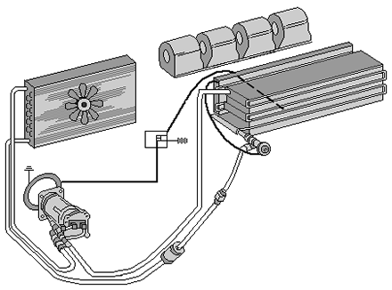
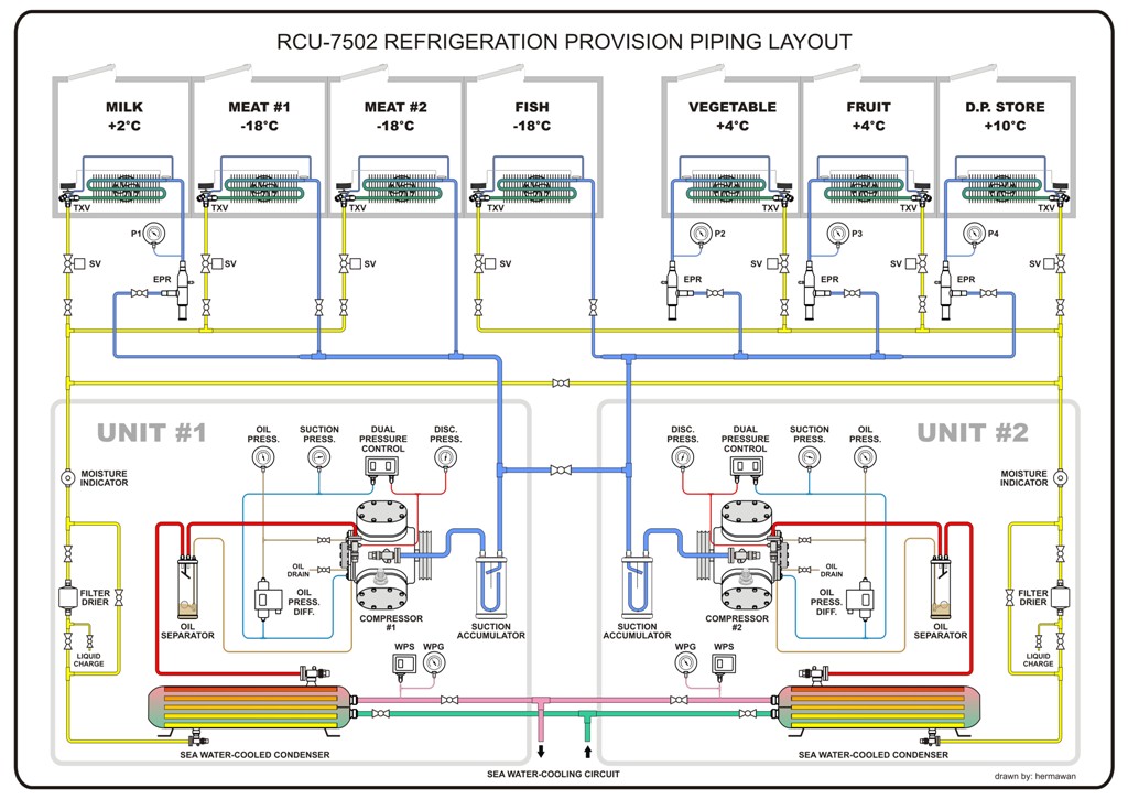
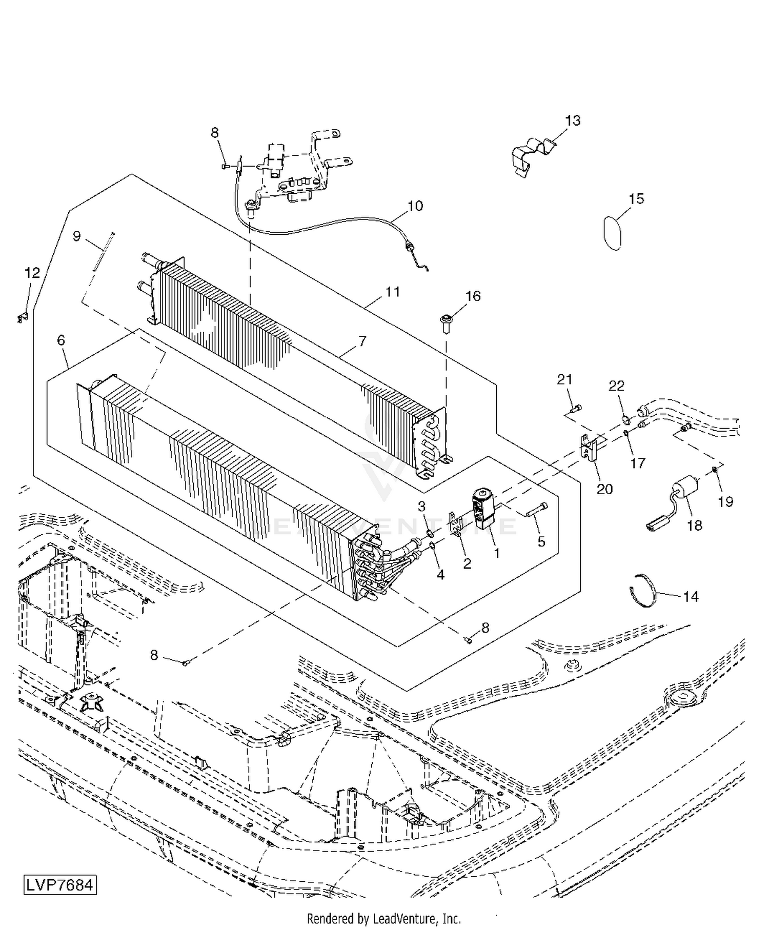
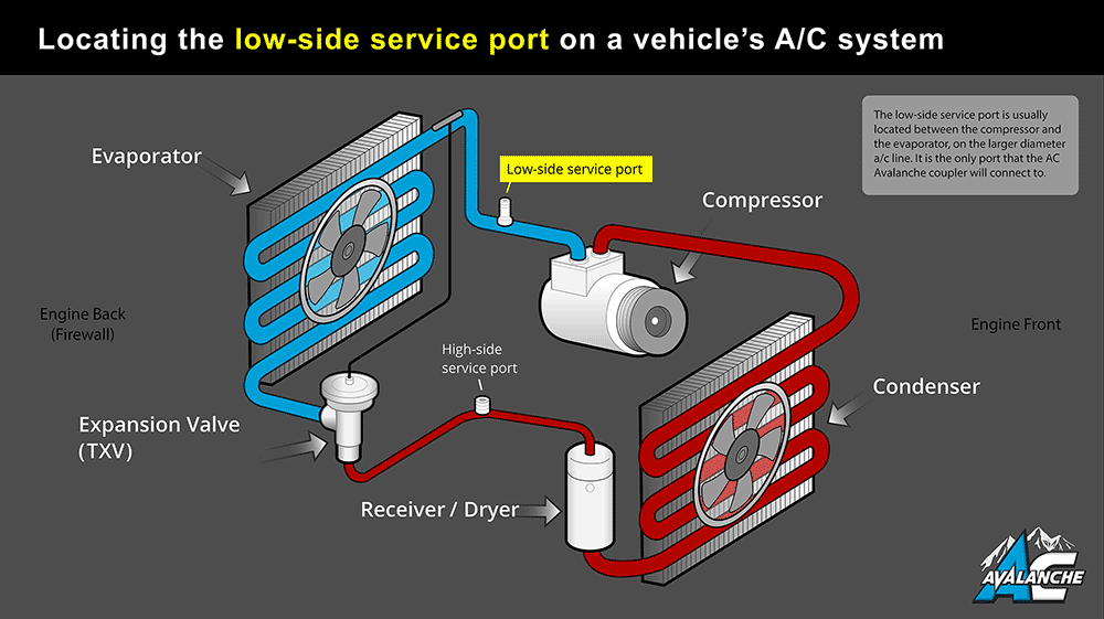
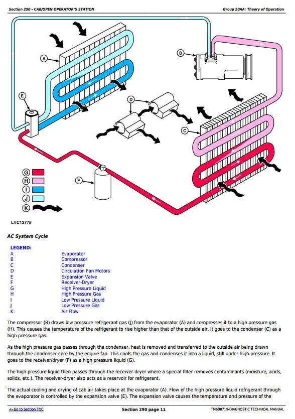
John Deere Parts Diagrams John Deere 6300 6500 6600 TRACTORS SOUTH AMERICAN EDITION -PC9559. Air conditioning repair on John Deere tractor required electrical repair with faulty thermostat detected then regas to correct levels. The solid red color represents high pressure liquid refrigerant.
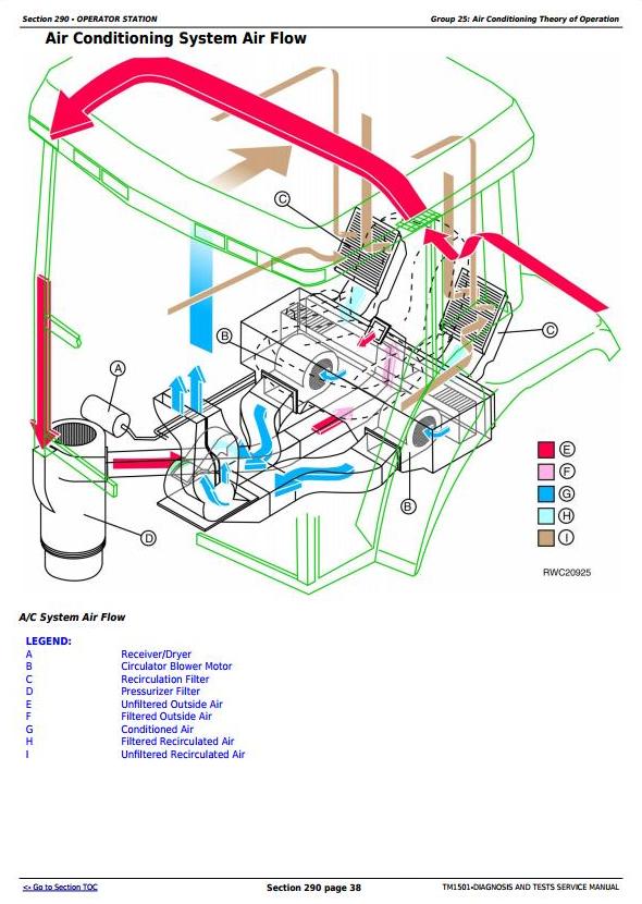
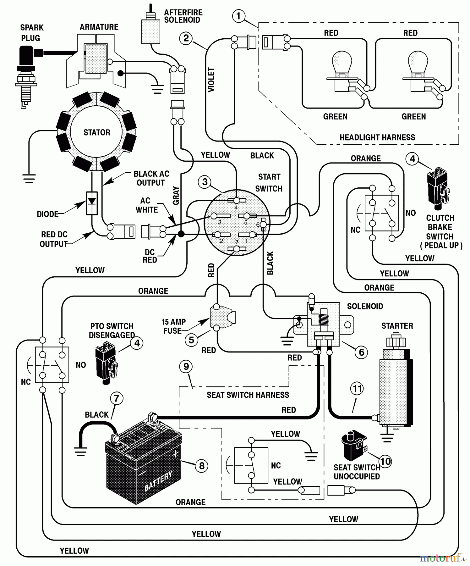
When recirculation air filters are plugged or have never been serviced the tractors AC system is forced to attempt to cool 100 percent of the outside air. A wiring diagram is VERY helpful here. Ford 7710 tractor wiring diagram in addition fasett info wp content uploads wiring diagram for ford 8n the wiring diagram readingrat of ford 7710 tractor wiring diagram along withgardentractortalk forums uploads monthly 04 2012 post 2253.
Air-cooling is mostly tractors of less horsepower motorcycles scooters small cars and small aircraft engines where the forward motion of the machine gives good velocity to cool the engine. We receive a lot of phone calls and emails from customers seeking help with their tractor issues. 7710 Ford Radiator 7710 Ford Fuel Pump 7710 Ford Engine.
Ford 7710 Tractor Wiring Diagram. Replace the filter element.
This is for a allis chalmers ca but frankly applies just fine to every old farmall ac case jd and many others.
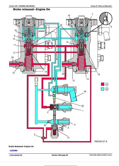
A wiring diagram is a streamlined standard pictorial representation of an electric circuit. AIR COMPRESSOR - COMPONENTS. The red dots inside the piping represent discharge vapor. Some of the most common issues are related to the tractors wiring. Replace the filter element. If not determine if the fuse servicing that component is blown or if the wiring feeding the compressor has developed a short. This is much more difficult than cooling a mixture of recirculated air and outside air. Wiring diagram farmall m tractor. Ford 7710 Tractor Wiring Diagram.
Had to do it in the early morning due to the AC not working. Eye 265 favorite 0 comment 0. This is for a allis chalmers ca but frankly applies just fine to every old farmall ac case jd and many others. If the compressors magnetic clutch is getting voltage but not engaging the clutch is likely defective and needs to be replaced. FARMALL 30A - COMPACT TRACTOR WROPS - TIER 4B NA 0815 - 0416 FARMALL 30B - COMPACT TRACTOR 0112 - 1214 FARMALL 30C - COMPACT TRACTOR WROPS - TIER 4B NA 0214 - 0117 FARMALL 31 - COMPACT TRACTOR 0108 - 1210 FARMALL 35 - COMPACT TRACTOR 0108 - 1210. In this article I will break down wiring theory and practices to its most simple and easy to. The red dots inside the piping represent discharge vapor.











Post a Comment for "Tractor Ac System Diagram"